This was a long project, starting last December and culminating in a finished device this December. A small device is responsible for interpreting an audio signal and producing a visual display on a strand of Neopixel LEDs. Neopixel LEDs are available in a Christmas light package from several vendors, so that is what I have used. The device itself is compatible with all 5 or 12V RGB WS2811 Neopixel controllers, so it can be used with a regular flexible Neopixel strip, too. Although the device supports both 12 and 5V strands, it does not perform voltage regulation for the strand power, so the power supply needs to match the Neopixel strand voltage.
In the current software configuration, the device supports two modes of operation. Its primary mode is a multicolor volume meter visualizer with adjustable gain. In the other mode, it functions as a simple rainbow sweep visual, scrolling through the color wheel.
In the volume meter visualizer mode, the height of the illuminated LEDs is a function of the total volume of the audio input and the illuminated color is a function of the frequency distribution. I developed the color mapping to work for most rock and roll music, so the colors are tuned between a low bass drum and a hi-hat. It displays red for low frequencies, green around middle C, and blue for high frequencies. The output color is a sum of the dot products of the frequency volumes and each of the red, green, and blue function maps. Practically, that means that if you were to listen to a high pitch and a low pitch at the same time, the LEDs would be purple. As is often the case, complex songs will have a wide array of frequencies that will result in a near-white display.
For the hardware and software source documents, check out my GitHub repository.
This is not the only Christmas tree visualizer, or even the first. I would argue that this is a better visualizer, since it is configurable by buttons, very small, and durable. I produced 20 prototype devices at a material cost of about $12/device (not including peripherals like the power supply and lights or the large amount of time that went into manual assembly).
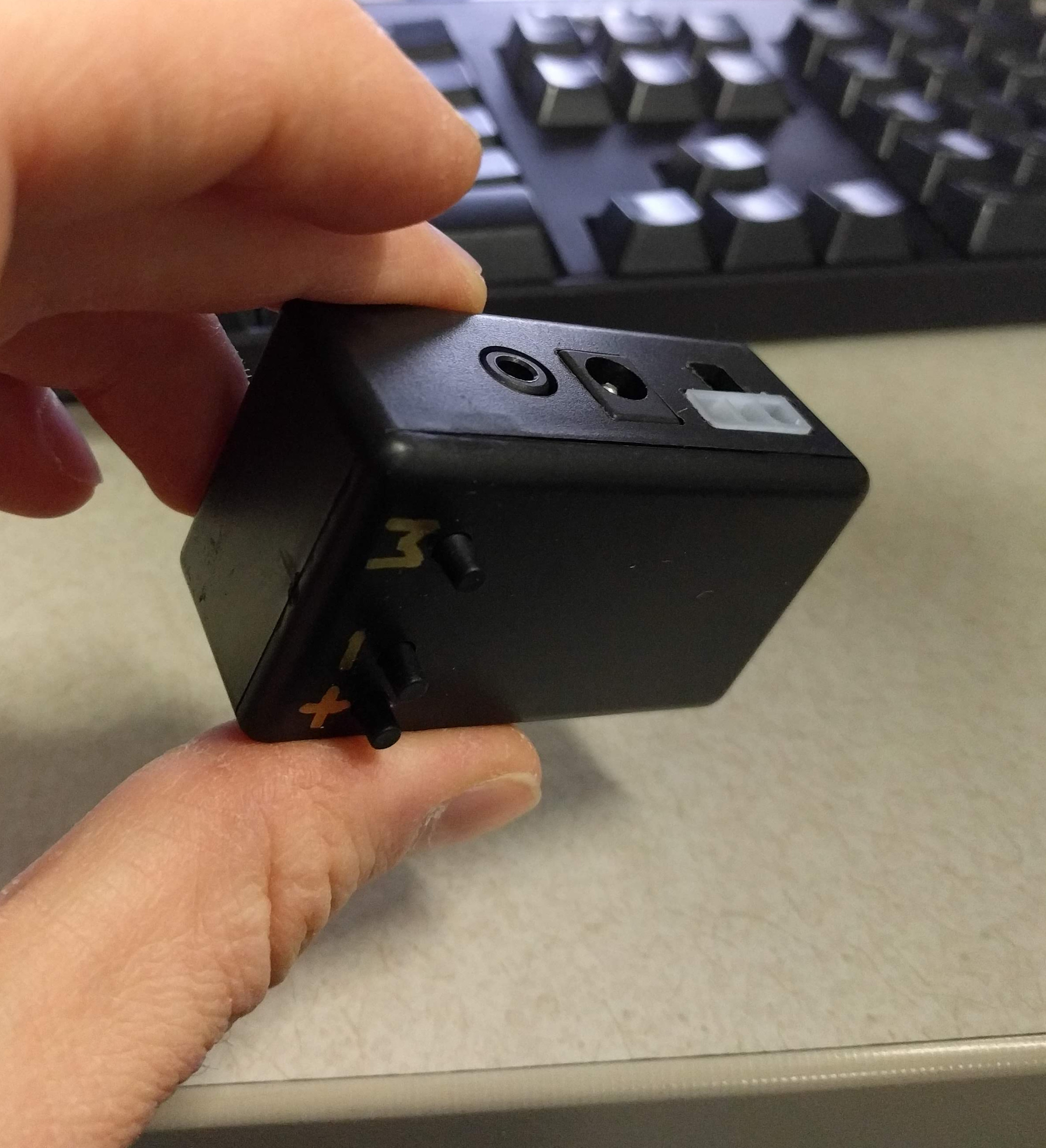
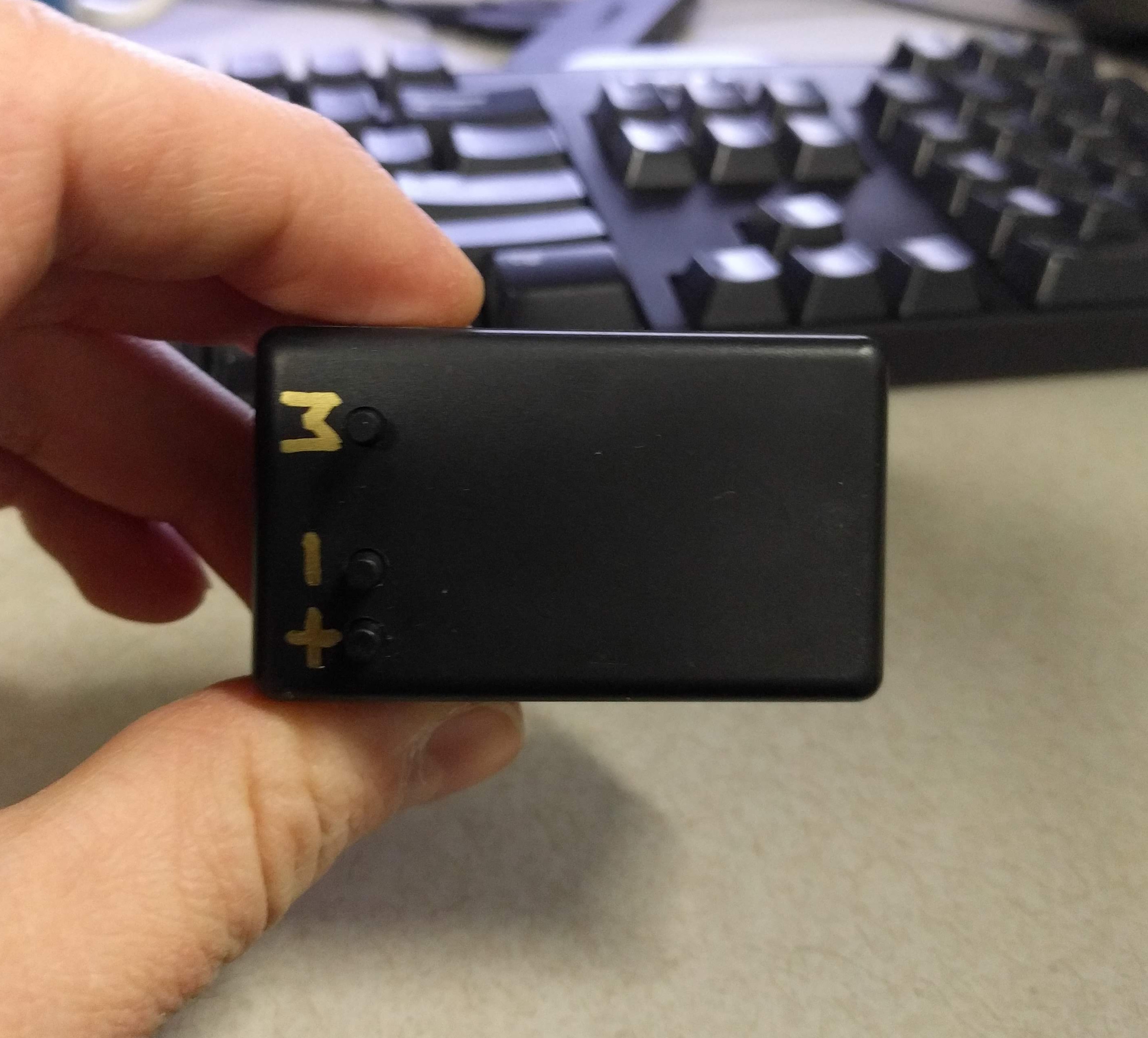
The circuit boards were designed to fit in a small, inexpensive project box available from a few vendors. Building controller boards to fit in existing boxes is a great way to save development cost if the shape of the box is not particularly important. The board is attached with two screws to standoffs in the lid of the box. I machined the connector holes in the body of the box on a vertical mill and drilled the holes for the buttons on a drill press.
The circuit board was designed to function as a drill pattern for the buttons. In the center of each button there is a small hole that can be used to align the pilot drill. This is a very simple and essentially free addition to the board, and it saves quite a bit of time creating a drill template by hand. Before I started machining I just set one PCB aside to use as a drill template. That one PCB probably cost $0.50 and adding the holes took almost no PCB design time.
![[Image of PCB]](https://www.ericmakeseverything.com/wp-content/uploads/2019/02/ECAD.png)
The controller is an Arduino clone built using an ATMega328PB microcontroller, which is available in a TQFP package and slightly cheaper than the ATMega328P in the TQFP package. The regulator on board supports 5-12V input. The microcontroller is responsible for driving the Neopixels and all calculations and visualization code. The meat of the frequency analysis is done by the MSGEQ7, a dedicated seven-band graphic equalizer chip designed by Mixed Signal Integration, of which Sparkfun appears to be the only distributor. This chip is responsible for about half of the board production cost, but it accomplishes all the band filtering that would otherwise be done in a larger footprint.
For the end user who wants to modify this device, programming is accomplished with the 6-pin ISP header. There is also a header row containing 5V,GND, TX and RX pins and headers for an additional digital IO and GND. There is a space removed from the corner of the PCB so that the end user can install some other component if they wish.